Improve business networks using cloud-managed solutions

Press play to listen to the article.
Cloud-managed solutions can be the right approach to improve business networks while reducing CAPEX and OPEX with open and disaggregated network solutions.
For many businesses, the hidden costs of dealing with underperforming on-premises or hybrid networks can represent a significant obstacle to surmount, especially with the current situation that requires more availability and everything managed remotely.
Because of the urgency of having reliable network connectivity, many businesses are becoming quicker to react to the situation by upgrading networks. However, the upgrade needs to be done smartly.
Nowadays, adopting a cloud-managed network infrastructure allows organizations to save a considerable amount of money and time. Primarily, organizations operating wireless infrastructure in multiple locations can take advantage of deploying WLANs in the cloud and drive all the IT team’s work remotely. Therefore, companies will rely on a high-quality wireless experience at reduced costs.
How to improve business networks efficiency with a cloud-managed platform?
First of all, managing your networks from the cloud implies having management software that allows you to operate and control networking devices and networks from a single dashboard. It should also let you overview the network’s health and enable you to troubleshoot instantly from the cloud if a problem arises.
The key features that you should be looking out for in a cloud management platform are:
Centralized management
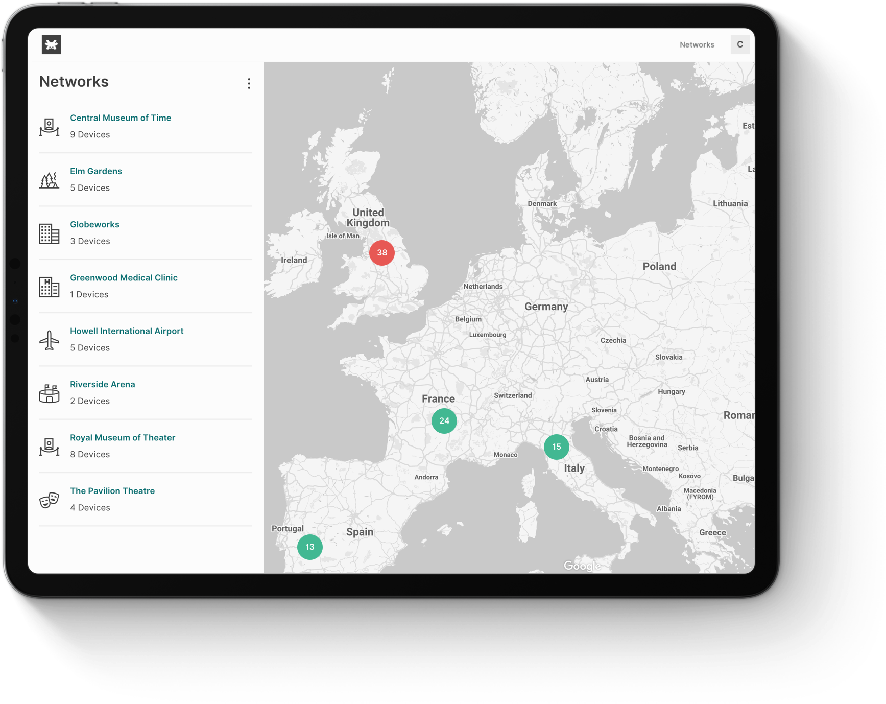
Operating networks in the cloud allows you to easily manage access points from any place, at any time. Through a single centralized dashboard, your management and monitoring processes are simplified, independently from where the access points are located.
Centralized management lets users configure and monitor multiple WiFi organizations and networks, networking devices, SSIDs, and clients from one platform. Also, you can configure the access points in the network in bulk. This feature guarantees an issue-free, fast and easy provisioning of new access points.
Remote management
The management of a network in the cloud allows, first of all, to control any operation remotely. Remote management facilitates real-time monitoring and troubleshooting, dropping the need to travel to the site in case of issues.
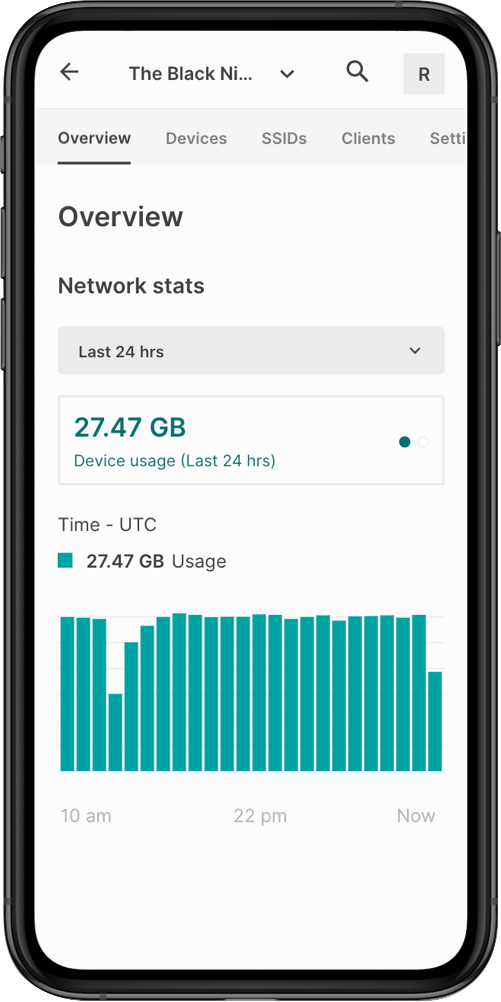
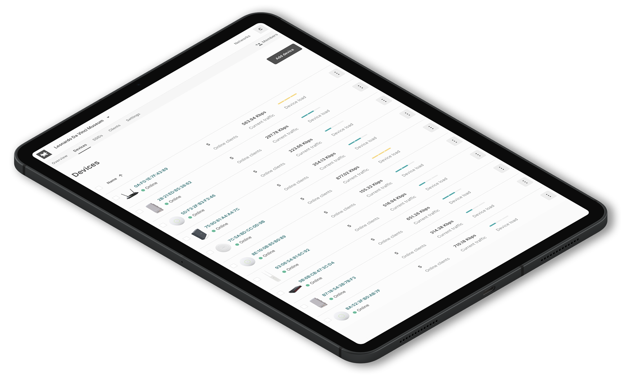
You can check how many client devices are currently associated with a WiFi SSID and how much bandwidth they are consuming. Also, you can track the network’s device traffic and monitor bandwidth demand. Oversee the access points’ health status, mostly if the number of connections requested for an SSID increase.
Zero-touch deployment
With cloud management, access points can connect automatically to the cloud, and there’s no need to provision them. Thanks to the zero-touch feature, installing a networking device without needing to configure it on-site is a piece of cake. A new device can be sent to a site already configured to mount and power it up by a local employee without IT-skills.
Manual configuration is complex, with a high predisposition to errors, costly, and time-consuming. Someone with the necessary configuration skills has to go on-site and set up the device before completing the central management system’s configuration.
This strongly reduces the lead time, the number of hours spent on installing and minimizes configuration errors.
Scalability
Cloud management offers highly scalable capabilities that are difficult or expensive to deliver on-site. In the cloud, you can start managing a low number of devices and scale over time when your business grows and needs to add more capacity.
The requirement of resources can be increased or decreased according to business needs. Furthermore, you expand your network without large capital investments, as cloud-based approaches are usually based on a pay-as-you-go structure or subscription plans. In this case, you only pay for the capacity used and do not incur unexpected costs.
The flexible pay-as-you-go formula is based on your request for a software budget easy to manage. You are charged for the number of access points connected to your network. With no limitations in the number of connected clients, networks, and locations. Therefore, software costs are manageable and predictable.
Simplified troubleshooting
Reduced hardware costs
With cloud-based WiFi management, CAPEX costs are considerably reduced. Indeed, you eliminate expensive hardware controllers in the network infrastructure.
Controller hardware devices, such as hardware controllers or cloud keys, represent a single point of failure. The entire system is at risk when a single element fails, as the whole remote visibility and centralized configuration capabilities get disrupted.
In a cloud-based environment, the access points will connect directly to the cloud infrastructure over the internet. There will be no need to have any intermediary device, such as a hardware controller. The management traffic is isolated from the users’ traffic and securely reaches the cloud.
The users’ traffic flows through and goes directly to the destination, invisible to the infrastructure. The cloud service may be free, freemium, or subscription-based. Therefore, differently from the hardware controller at a higher cost, the cloud-based management solution gives businesses more adaptability to their budgets.
Reliability
Tanaza is the ideal cloud-managed solution to operate your WiFi networks and improve your business networks.
Tanaza WiFi cloud management is the perfect alternative to the outdated on-premises deployments. Tanaza relies its cloud platforms on the robust Amazon Web Services (AWS). The highest security levels available on the market are guaranteed while running on a robust cloud infrastructure.
The Tanaza platform is the cloud-based WiFi management software that makes deployment, configuration, and remote monitoring of networks easier. The core technology, TanazaOS, is based on the reliable and powerful Linux-based Operating System, which is compatible with multiple WiFi access points.
TanazaOS is extremely fast in sending configurations to the access points. The most complex network-wide settings are applied to all access points within a network in less than 5 seconds. It is also secure, as it is built on the most recent kernel and bootloader.
The Tanaza WiFi cloud management platform offers remote provisioning, monitoring, and troubleshooting of every device. Network administrators can set the network’s basic configurations, applied by default to all the cloud-managed access points in that network. And reconfigure access points without rebooting them or restarting the services, all from one dashboard.
Tanaza allows businesses to improve their efficiency levels. The software enables them to manage all their WiFi networks, access points, SSIDs, and clients from one single platform in the cloud.
Discover the full feature set of Tanaza WiFi cloud management software.
Reduce CAPEX and OPEX with Tanaza Powered Devices.
Tanaza gives customers the flexibility to choose the WiFi access points that best meet their needs. Tanaza has a curated selection of access points, with the TanazaOS software already installed. The Tanaza Powered Devices are suitable for professional medium and large-scale deployments.
Also, Tanaza has a list of devices compatible with the platform. Users are free to mix different brands within their network deployments. Discover all the devices that work with Tanaza.
Request a 15-day free trial
Related articles:
Public Cloud vs Hybrid Cloud vs Private Cloud – What is the best choice?
https://www.tanaza.com/blog/how-to-optimize-wifi-network-infrastructure/